Domain-driven design (DDD)
Domain-driven design (DDD) was popularized by Eric Evans in his 2003 book of the same name, and which is colloquially referred to as "the blue book". The concepts behind DDD predate the book, but Evans brought them together into a coherent architectural pattern and design process.
Evans observed that good software tends to closely model the human processes that it automates or the real-world problems that it solves. It follows that the first job of a software developer should not be to write computer code, but to understand the domain of the software. Domain-driven design enforces this by putting a model of the domain at the center of the software design.
Domain-driven software designs are built around models of their business domains or problem spaces, the subject areas of the software.
DDD is analogous to physical architecture. Architects design buildings to serve specific functions. The blueprints for a public library and a private home will therefore look very different. Domain-driven design takes this principle and applies it to software. Thus, the blueprint for a banking application should look like the departments and procedures of a high street bank, while the blueprint for an e-commerce application should resemble the operating model of a bricks-and-mortar shop. Likewise, bespoke enterprise application software should model the very businesses that own it.
DDD rejects the process of reusing generic architectural patterns like [model-view-controller] and forcing entirely different applications to fit the same ready-made floor plans. Instead, a domain-driven design approach to software involves creating a unique architecture for each application, one that is tailored to the specific business domain it serves by constructing the system around representations of objects and events that exist in the real world.
To design and build high quality domain models, close collaboration is required between the technical experts (who implement the software and hardware) and the domain experts (aka. subject matter experts or business stakeholders). The two parties are jointly responsible for iteratively refining the conceptual model of the solution. This is one of the most powerful aspects of domain-driven design: that development of software is equally driven by software developers and the customers/users (or representatives of them, such as a product manager).
DDD is particularly beneficial in complex problem spaces – things like banking applications and air traffic control systems – or where the business domain is not well understood. Domain-driven design emphasizes the design of a system’s essential complexity, the stuff that is essential to the business itself. This process helps to clarify the business domain, to identify the key concepts and relationships within it, and to build a shared understanding of the domain between the technical and business people.
DDD may introduce unnecessary accidental complexity for small, simple software systems. Also, it is often difficult to retrofit domain-driven design patterns to existing systems. That’s because domain-driven design cuts across the whole design of a software system, informing the underlying structure of the codebase and the communication patterns between components.
DDD can be described as an architectural style, a design philosophy, and a design process. As an architectural style, DDD is a set of recommended design patterns for composing software systems. As a design philosophy, DDD is about building software that closely models the business domain it serves, and creating a shared understanding of the domain between technical and non-technical stakeholders.
But DDD is (perhaps) most useful as a software design process. Evans described the process of DDD as having two distinct stages:
- Strategic design, in which the domain is modelled.
- Tactical design, in which the domain model is implemented in code using a variety of object-oriented design patterns.
Strategic design
Implementing domain-driven design in software projects requires a deep understanding of business needs and a clear strategy to effectively model the domain. This work is carried out as part of the strategic design, which is the first phase of a domain-driven approach to software design and which will typically be undertaken during a project’s [discovery phase].
Fundamentally, DDD is all about good domain modeling. The goal of the strategic design is to end up with a high-level model of the business domain. The model is created by the technical experts but its design is driven by the people who know most about the domain – the domain experts. The model is discovered through conversations with the domain experts. The technical experts collaborate with the domain experts through continuous conversation and feedback to create a model of the problem space that makes sense to all the project’s stakeholders.
This is pure business exploration. Methodologies used to discover the domain may include Big Picture, Process-Level Event Sourcing, Domain Storytelling, and EventStorming. The strategic design is normally an [iterative and incremental] process, because it is normally difficult to create from the start a complete model that covers all of a business’s needs.
The objective of DDD is to produce software that the domain experts would make if they had the technical know-how to do it themselves.
The emphasis on continuous conversation and close collaboration between technical and non-technical stakeholders brings other advantages. Often the process of automating business processes through software development can yield new insights into the business itself. The process of continuous integration brings a continuous [feedback loop] of fresh insights. And domain modeling also serves the purpose of pooling knowledge within an organization, such that knowledge of certain aspects of a business and its IT systems are not restricted to particular tribes within the organization. Instead, knowledge is dissipated throughout the organization.
The outcome of the strategic design phase is a comprehensive model of the software’s domain or problem space. Domain models may be expressed in documentation, code, tests, or visually (eg. using UML or similar graphical notations), or a combination of all these. DDD is not prescriptive about the choice of modeling artifacts. The only criteria is that a consistent language – an ontology – is used throughout the model.
Ultimately, the domain model will be implemented in code. So a good modeling process needs to consider not only the domain but also its implementation in software. It is important that models can be translated into working code. It is possible that a model that is truthful to its domain could have serious problems in its implementation, such as unacceptable performance. For this reason, domain modeling and system design should run concurrently.
Throughout the [construction phase], the software developers should make frequent references to the model. The software system should map the model in a very literal way, going as far as using the same language to name things like classes and methods.
Developers should have ownership of the model, and responsibility for its integrity. Changes to the model should be reflected in code, and vice versa.
Domain
The first step to creating a domain model is to define the domain. The domain is the subject area of the software. The domain is taken from a sphere of knowledge in the real world, or a set of business processes that the software is intended to automate.
Examples of domains include customer relationship management, financial loan application management, video subscription services, and so on.
Defining the domain is as much about defining what the software will not do as what it will do. The domain is the boundary within which the software will operate, or the context in which the software will be used.
Subdomains
Once the scope and boundaries of the application are defined, the second step is to discover the subdomains. A subdomain is a smaller, more specialized area within a domain. Each subdomain has a specific purpose or represents a particular business capability. For example, in a video subscription service, the billing, video streaming, and user management areas might be subdomains.
A subdomain is something that exists in the real world and shows how the business operates in a given area.
Subdomains may overlap, and they may even be nested. Some processes in a subdomain may be part of larger processes in another subdomain, which itself might touch several other subdomains. However, as we shall see, different subdomains may need to have their own models (including their own ontologies), and therefore the strategic design should prioritize simplifying the domain. Having fewer subdomains, and a simple hierarchy of subdomains, means there will be fewer dependencies between subdomains, and the essential complexity of the eventual system will be minimized.
Some subdomains will be core subdomains. In a video subscription service, the core subdomain would probably be video streaming. DDD emphasizes that the core subdomain(s) should be the focus of the design, while secondary subdomains should be as simple as possible and exist only to support the primary ones.
Key parts
The third step in the strategic design is to work out what are the key parts within each subdomain. For example, if we look at the billing subdomain in our theoretical video subscription service, we might identify accounts, payment details, and subscription plans as the key parts of that subdomain.
@startuml

top to bottom direction

rectangle "video subscriptions" {

  rectangle "user management" {
    rectangle "subscribers" {
    }
  }

  rectangle "video streaming" {
    rectangle "videos" {
    }
    rectangle "viewers" {
    }
  }

  rectangle "billing" {
    rectangle "accounts" {
    }
    rectangle "payment details" {
    }
    rectangle "subscription plans" {
    }
  }

}

@enduml
Some key parts will be common across multiple subdomains. For example, subscribers will probably be a key part in most subdomains. But a sign of good strategic design is when each subdomain has at least one key part that is unique to it, and not shared by other subdomains. For example, the billing subdomain might have a "payment details" part, which you would not expect to see in any of the other subdomains.
Bounded contexts and their ubiquitous languages
DDD encourages developers and domain experts to collaborate together and develop a common language to describe the whole business domain. The objective is for domain terminology to be understood and used consistently by all stakeholders in a software project – both technical and non-technical stakeholders.
DDD calls this common language the ubiquitous language. It is similar in concept to an ontology. The language is taken from the real world business domain, and it should be used to specify software requirements and to name things in the application code and its tests. Indeed, the domain language should be used in all forms of communication (both written and verbal) between the technical teams and the domain experts.
Ideally, there would be a single unified model covering the whole business domain. However, in complex problem spaces, this is often unrealistic. Different subdomains may need to have different models, each with its own distinct language. For example, in the billing subdomain, subscribers might be referred to as "accounts", while the video streaming subdomain might refer to them as "viewers", and the user management subdomain might use the term "subscribers". Thus, the terms "account", "viewer", and "subscriber" all refer to the same type of entity, and only the language changes depending on the context. (Variations in language are most likely to appear in the key parts of subdomains.)
Similarly, the representations of real-world entities, events, and other concepts may differ between subdomains. For example, in an e-commerce domain, a "customer" entity within the "support" subdomain might encapsulate a user’s order history and support tickets, while the equivalent entity in the "finance" subdomain might encapsulate the same user’s payment history, invoices, and method of payment. Thus, the same entities might have different attributes and methods depending on the subdomain.
DDD recognizes that different subdomains may need to have different models, each using different terminology for its key parts and different representations of the same real-world objects.
Although variations in the domain model increase the complexity of a system’s design, domain-driven design advocates that domain models should be accurate representations of their real-world counterparts.
Domain-driven design introduces the concept of bounded contexts to manage this complexity. A bounded context is a specific part of a business domain that has its own domain model. Within a bounded context, the domain objects are consistent. And the language is consistent too. There is only one term per concept. Thus, within a bounded context there is a ubiquitous language.
A bounded context may span a single subdomain, or it may span several. In most cases, there will be a 1:1 mapping between subdomains and bounded contexts, and therefore the two terms are synonymous. However, in some cases it may make sense to combine multiple subdomains into a single bounded context. This tends to be particularly beneficial where two or more subdomains have significant interdependencies.
So, bounded contexts explicitly define the context within which a discrete domain model applies. They should also be used to define the scope of responsibilities of teams. Bounded contexts should also be used to set boundaries for team responsibilities, and physical manifestations of that included codebases and their repositories, development and testing infrastructure, and deployment pipelines. Ideally, each team will be responsible for, and have a high degree of autonomy over, a single bounded context – which may span multiple subdomains, but which will have a consistent domain model throughout.
Each bounded context should have a name (which may be reflected in team names), which should be part of the domain’s ubiquitous language. Tools such as a Bounded Context Canvas may be used to help define the bounded contexts and their ubiquitous languages.
Context maps
The final part of the strategic design is to learn how the various bounded contexts interact with each. This is about defining the relationships between different parts of the business domain, and it is done by creating a context map. This is a visual representation of communication paths (and directions) between the bounded context and the subdomains they encapsulate.
It is through the context maps that teams understand how their parts of the system fit into the bigger picture. The context maps also define how the different models of each of the bounded contexts relate to each other.
For example, imagine that a video streaming context needs to know what quality of video to stream to a user, and since this is dependent upon the subscription plans encapsulated in the billing context, the video streaming context will need to communicate with the billing context. Therefore, there will need to be a mapping between a viewer in the streaming context and the subscriber in the billing context. In code, this transformation of models between contexts is done using some sort of anti-corruption layer (ACL) at the interfaces between subdomains. Each subdomain’s user interface is responsible for ensuring that nomenclature from other contexts do not pollute its own bounded context.
Evans defined a set of named patterns for describing the relationships between bounded contexts on a context map. These patterns describe both the technical integration strategy and the organizational dynamic between the teams responsible for each context:
- Partnership — Two teams coordinate planning and release together because their contexts succeed or fail together.
- Shared Kernel — A small, explicitly bounded subset of the domain model is shared between two contexts. Both teams must agree on changes to the shared kernel.
- Customer/Supplier — An upstream context produces output that a downstream context consumes. The downstream team acts as a "customer" with some influence over the upstream team’s roadmap.
- Conformist — The downstream team has no influence over the upstream team and chooses to accept the upstream model as-is, eliminating the need for translation.
- Anti-corruption Layer (ACL) — The downstream team builds a translation layer to isolate their model from the upstream model. This is the most defensive pattern.
- Open Host Service — The upstream context publishes a well-defined protocol or API that multiple downstream contexts can integrate against directly.
- Published Language — A well-documented shared language (eg. an industry data standard) serves as the common medium of exchange between contexts.
- Separate Ways — Two contexts have no integration at all; each team finds independent solutions within their scope.
- Big Ball of Mud — A context boundary is drawn around a legacy system with no clear internal model, to prevent its disorder from spreading.
Bounded contexts and context maps help to make sense of the essential complexity that is inherited from a system’s business domain. Tools such as the Context Mapping DSL (CML) may be used to document the models of bounded contexts and to map the relationships between them.
Usage of bounded contexts and context maps is particularly beneficial for moderating accidental complexity that would otherwise arise through [evolutionary design] over time. For example, imagine that an insurance business acquires a competitor, and begins the process of integrating their disparate IT systems. Although the domain is the same (insurance), the two companies will likely have modeled their domain entirely differently. They will each have developed different business rules, terminology, and actors. Therefore, rather than try to integrate the two systems into the same domain model, it may make sense to keep them separate – at least initially. Wrapping each model in a bounded context and using a mapping system to translate between the two models is a great solution for managing this sort of emergent complexity.
What makes a system is complex is not so much the number of subdomains, but rather the number of bounded contexts, and the complexity of the mappings between the contexts. Ideally, a system will have as few bounded contexts as possible, and the mappings between them will be simple, such that domain objects are largely consistent throughout the whole system.
Tactical design
With the domain model complete, the domain-driven approach to software design moves on to implementing the domain model in code. A variety of object-oriented design patterns are used for this purpose. This second phase of domain-driven design is called the tactical design.
Whereas the strategic design is very much a business discovery process, the tactical design is more of a technical design process. Another way of thinking about it is that the strategic design produces a [conceptual architecture] for the solution, while the tactical design fleshes this out into a more detailed [logical architecture].
DDD provides a set of object-oriented design patterns that can be used to create a set of [domain objects] within each bounded context. Object-oriented programming is particularly well suited to [model-driven design], much more so than [procedural] and other programming paradigms that do not tend to provide sufficient [programming constructs] to reflect complex models.
The domain objects will typically be used to represent the key parts of the strategic design. The two main design patterns recommended for creating domain objects are [entities] and [value objects]. Other tactical patterns include [aggregates], [repositories], and [services].
Domain objects are scoped to bounded contexts. Thus, if a bounded context is composed or more than one subdomain, the subdomains within that context will all share the same set of entities, values, and other domain objects.
The tactical design patterns recommended for domain-driven design are entirely optional. Ultimately, as long as a clean domain model sits at the centre of an application’s architecture, the application can be said to follow a domain-driven design. DDD is most powerful as a conceptual framework for thinking about the process of designing software. DDD also proposes a series of architectural design patterns, but other patterns may be more appropriate, depending on the problem being solved by the software.
Design patterns
DDD provides building blocks for implementing a domain-based architecture in code. The building blocks are a suite of recurring design patterns that exist in different conceptual layers of an application’s code structure.
DDD design patterns include:
- [Aggregates]
- [Commands]
- [Domain events]
- [Entities]
- Factories
- [Modules]
- [Repositories]
- [Services]
- [Value objects]
Commands
Commands represent a system’s use cases. These are the things that the system can do. Commands are typically implemented as classes or methods that encapsulate the logic for a particular operation.
The commands act on domain objects, which implement the business rules and data structures required to fulfill application operations.
Domain objects
In domain-driven software, the domain is modeled using [domain objects] and [domain events]. The domain objects are implemented using a variety of object-oriented design patterns, notably entities and value objects, and aggregates of both.
Domain objects are units of code that encapsulate business rules and data structures that are taken from the real-world business domain. For example, in a domain with users and teams, the software would probably have a User entity and a Team entity, and perhaps a JoinTeam service that would encapsulate the logic that encodes policies about which users are allowed to join which teams.
Entities are representations of things in the real world, such as users, teams, videos, and channels. Entities tend to persist after their destruction in memory, and the identity of each entity remains consistent throughout the lifetime of the system, even if instances of an entity are created and destroyed, and even it its attributes change. This is achieved by giving each entity a unique, immutable identifier. Thus, even if two objects have identical properties, they are considered to be different entities if they have different IDs.
Entities are mutable. Their attributes can be changed – except for their IDs. For example, a subscriber may change their email address, but it’s still the same subscriber because its ID does not change.
Ideally, the unique identifier for an entity type would be a business concept, such as a bank account number for bank account entities, or a customer number for customer entities. If no such permanent identifier exists in the real world, a unique identifier should be generated by the system. Technical identifiers are often used in practice, such as UUIDs or auto-incrementing integers.
Entities are typically generated at runtime from external input – end users, databases, etc. – and therefore entity classes should not assume that the data provided to construct them is valid. Therefore , entities will often have built-in runtime validation checking to ensure that all instances are always in a valid state. Modeling using these design constraints can help to enforce data integrity, not only of the application’s dynamic state, but also of the static data that is stored in persistence systems (eg. databases).
Not all domain objects need to be modeled as entities, because not all domain objects will need a unique identity or need to be persisted. If all we are interested in is the values or attributes of something, then value objects can be used.
Value objects are objects that represent a simple value in a domain model, such as a date or a price. A value object has attributes like an entity, but unlike an entity a value object does not have a conceptual identity. Two value objects with the same internal attributes are considered to be equal, and therefore value objects (unlike entities) cannot be considered to be unique.
As with entities, the values of value objects may be considered to be always "correct", since validation should be done at construction of the objects. But unlike entities, value objects should be modeled to be immutable. Thus, if you need to change a value object, you create a new one.
Entities may be [composed] from one or more value objects. For example, a subscriber may have a name, email address, and date of birth – all of which could be implemented as value objects. You could use the native types of the programming language to model these values, but by creating value objects you are explicitly stating that a value is an important part of the domain model. By comparison, implementation details such as the "last modified date" of an entity may not be considered important enough to be a value object. If the values are not relevant to the domain but are required only to implement the software, we may call these technical values.
Whether a piece of data should be modeled as an entity or a value object is not always a clear-cut decision. For example, an address could be modeled as either (value objects do not have to be restricted to a single value). In general, if something is important to the business it should be modeled as an entity. For example, in a real estate application, addresses may be important enough to be modeled as entities. However, if the address is just a way to contact a customer, it may be more appropriate to model it as a value object.
A complete domain model is made up of a mix of entities and value objects. Typically, you will end up with a lot more value objects than entities, but this will vary between domain models.
Some domain models may required that related entities and value objects (and perhaps other structures, too) be grouped together. This is where the aggregate pattern comes in. An aggregate is an object that encapsulates multiple related domain objects (composition). Each aggregate has exactly one root entity, which provides a single point of entry to the whole group of objects. The root entity guarantees the consistency of changes made to all domain objects within the aggregate, and restricts external objects from holding references to its member objects.
An example of an aggregate would be a Customer entity that internally references lots of other entities and values objects that represent things like a PhoneNumber, PostalAddress, EmailAddress, and so on. From an external point of view, the Customer entity is a single unit of code, and all the other objects are hidden from view.
Like entities, aggregates have unique IDs.
Finally, [collections] may be used to group together multiple instances of the same domain object types, and factories may be used to encapsulate the initialization logic for any domain objects or domain collections.
Domain events
Domain events are a way of representing things that happen in the domain. They are used to model things that happen in the real world, such as a customer placing an order, a product being shipped, or a payment being made.
Domain events are emitted by a component as a message that is somehow communicated with the rest of the application. Other components of an application may or may not handle the events when they receive them. Commonly, domain events will trigger additional domain events being generated by other components. For example, a domain event for a user being assigned to a department may trigger a domain event for the department’s payroll system to be updated. Other domain events may trigger processes such as invoicing, notifications, or inventory updates. Thus, complex business functionality is composed by having lots of independent services handle specific domain events.
// Headers
{
  "eventName": "UserPlaced",
  "id": "123456789",
  "datetime": "2025-03-10T12:00:000Z"
}

// Payload
{
  "departmentID": "6789"
}
Domain events are not emitted because of database changes. Rather, they are emitted before or during them, reflecting business decisions.
It is useful to distinguish between two categories of events:
- Domain events signify something meaningful that happened within a specific bounded context. They are scoped to that context and are primarily consumed by listeners within the same service or module. Because the consumers are close by and their needs are well understood, domain event payloads tend to be small, carrying only the information necessary to react to the occurrence.
- Integration events communicate changes across bounded contexts. They are the mechanism by which separate parts of a distributed system are kept in sync. Because the consuming contexts may have differing, and less predictable, needs, integration event payloads tend to be broader – sometimes overcommunicating to ensure all relevant information is available to any listener. Integration events are typically published over a message broker.
Domain events are distinct from technical events, which are used to represent things that happen in the software itself, such as a user clicking a button, a database query being executed, or a message being sent over a network. Technical events are important. They often need to be logged and monitored. But they should not be part of the domain model.
Services
Where business logic does not have an obvious home in any particular type of domain object, or if the logic is required to act on multiple domain objects, then a domain service may be used to encapsulate that logic. For example, consider the task of transferring money from one bank account to another. Putting such behavior in the entities for either the sending or receiving account feels misplaced. This is a business process that does not, conceptually, belong to any particular bank account. Moving this functionality to a separate service that acts upon both the entities for the sending and receiving account makes more logical sense, and it removes the need for circular dependencies between the entities.
Services are stateless (they do not have attributes of their own, so they have no internal state). They are used only to facilitate processes and tasks that act on domain objects. Domain services may also emit domain events.
Other types of services may exist in other (non-domain) layers of an application’s architecture. Infrastructure services may be used to interact with external systems such as message queues, and application services may prove beneficial to remove complex business logic from commands. For example, if a use case requires the orchestration of multiple tasks, this logic should be extracted to an application service, which becomes a dependency of the command that implements the use case.
Repositories
While factories are responsible for creating new domain objects, repositories are responsible for fetching and persisting existing domain objects.
A [repository] is an abstraction of a persistent container or storage layer – usually a database system and any attached caching systems. The repository pattern acts as a mediator between the domain and the data mapping layer, providing an abstraction that allows handling the collection of entities as if it were a collection in memory. It enables operations such as searching, inserting, and deleting entities without exposing details of the persistence implementation.
The repository pattern hides the implementation details of the underlying persistence infrastructure from the high-level application code and domain logic, and also encapsulates things like security credentials and transaction management. The repository pattern gives the illusion of simple in-memory collections. Different repositories (for different types of domain objects) will have similar APIs, but internally they may use entirely different strategies for fetching and persisting objects.
Data wrappers ma be used to pull entity data from persistence, while identity maps may be used to cache entities in memory (so there can be only one instance of an entity in memory at a time).
Modules
Groups of related aggregates, entities, value objects, factories, repositories, and services may be packaged into modules. A module exposes a single interface through which other modules can interact with all the objects within it, simplifying the overall system design where there is a lot of complexity in the interactions between domain objects.
Layered architecture
Systems built around domain-driven design principles have a [layered architecture] consisting of four main [conceptual layers]:
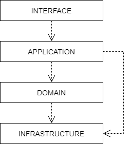
The idea is that within each layer are components that change for the same reasons. Thus, components within the interface layer should change only when there is a [change request] for how clients – users or other programs – interact with the application, while components within the infrastructure layer should change only when there is a change in some external system on which the application depends.
The most important design principle here is to try to keep the domain logic isolated from all other other concerns of the other layers. The objective is to avoid business logic getting scattered throughout a codebase, eg. embedded into UI widgets and database scripts. This sort of technical debt makes a system hard to change and to test.
The interface layer
The outermost interface, presentation, or UI layer deals with input and output.
This layer is responsible for interpreting user input commands and presenting the system’s response to the client. This layer defines all the entry points to an application, and typically includes routing rules, view templates, UI controllers, and middleware.
The interface layer should not have any knowledge of business rules, use cases, persistence technologies, etc. It should only receive client input (eg. URL parameters) and pass these to the relevant commands or event handlers in the application layer.
The application layer
The interface layer interacts with the lower application, services, or commands layer.
This layer defines everything that the application does as a series of commands, and message or event handlers. Overall, the application layer defines all of the use cases for the application.
The use cases will act on the domain objects and domain services in the domain layer below. The application layer should not do any processing directly, and it should not hold any state. Rather, the application layer is merely a thin [mediator] between the interface and domain layers. It is responsible only for delegating the processing of input to the appropriate domain objects or domain services, and for returning the output of those objects and services to the interface layer.
The domain layer
The domain or business layer is the foundation of domain-based architecture. It encapsulates domain objects, domain events, and domain services, which together model the business domain.
The command and event handlers in the application layer above tend to map to domain services in the domain layer, which in turn act on domain objects – aggregates, entities, and value objects.
The domain layer is the most important layer in a domain-based architecture.
The infrastructure layer
Where domain objects and services need to fetch data and state from external systems – such as databases, local file systems, third-party web services, and also system software dependencies – access to these things should be provided via abstractions sitting in the infrastructure or framework layer.
This is the lowermost layer of the application architecture, and it’s the boundary to all the external systems on which the application depends. Objects here provide abstract interfaces to vendor libraries, system software, databases, email transport agents, message queues, and so on.
A common feature of this layer is the existence of the repository pattern, which is used to query and persist state stored in external systems such as databases.
Other layers
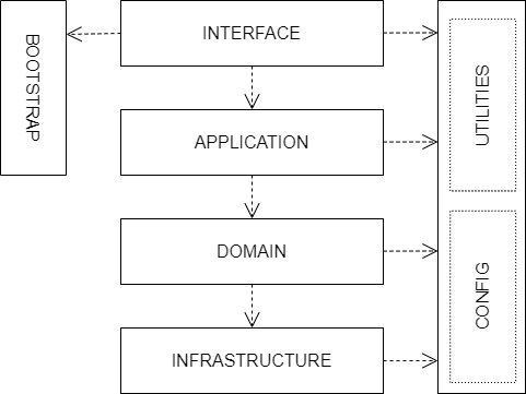
The interface, application, domain, and infrastructure layers are the four main layers of a domain-based architecture. But additional layers may be added as required.
For example, it is not unusual for applications to require some amount of generic bootstrapping code, environment-specific configuration, and access to general-purpose utility functions. These sorts of concerns may be encapsulated in their own layers, and may be used by all other layers.
Boundaries between layers
A key design constraint of domain-driven architecture is that each layer should only have knowledge of the layers below it in the hierarchy. Or, to explain it another way, software components within a layer should be accessed only by components in a layer above it. (Dependencies may skip layers. For example, components in the application layer may interact with both domain objects and abstractions of the infrastructure. For example, an application service for sending a user an email message may have dependencies on both a UserEntity domain object and an EmailTransportService.)
The domain layer should be isolated further by not having any direct dependencies on the infrastructure layer below it. This can be achieved by implementing inversion of control patterns at the boundary between the domain and infrastructure layers. Interfaces and [adapters] are commonly used for this purpose. The interfaces belong to the layer above (the domain layer), and the adapters to the layer below (the infrastructure layer). The interfaces define the dependencies required of the domain objects, domain events, and domain services. The adapters implement those interfaces. (And the responsibility for mapping interfaces to adapters may be delegated to a dependency injection container.)
Commonly, domain objects will interact with repository instances from the infrastructure later. Thus, the interfaces of repositories should belong to the domain layer, while the implementation of repositories belongs to the infrastructure layer. The domain therefore defines the methods and parameters that it accepts for repository access, but the implementation details of the persistence technologies are kept out of the domain layer.
The purpose of this design constraint is to enforce good separation of concerns, which in turn promotes loose coupling. In particular, it is important that domain logic does not get scattered throughout a codebase – coupled to parts of the UI or database queries, for example.
References
Books
- Domain-Driven Design: Tackling Complexity in the Heart of Software, Eric Evans, 2003 — aka. "the blue book", the original book on domain-driven design, and which remains the canonical reference resource for it.
- Domain-Driven Design Quickly, Abel Avram and Floyd Marinescu, 2006 — A free digital book from InfoQ – basically a condensed version of Eric Evans' original book, which helped to accelerate the early adoption of DDD.
- Domain-Driven Design Reference: Definitions and Pattern Summaries, Eric Evans (2015) — Evans published this free PDF as a reference guide to the key DDD concepts.
- Implementing Domain-Driven Design, Vaughn Vernon, 2013 — aka. "the red book".
- Domain-Driven Design Distilled, Vaughn Vernon, 2016 — Follow-up to "Implementing Domain-Driven Design".
- Domain-Driven Design in PHP, Carlos Buenosvinos, Christian Soronellas, and Keyvan Akbary — Real examples written in PHP showcasing DDD architectural styles. Extended examples, including fully-working applications, are available from the book’s Github page.
Blog posts
- Domain-driven design even more relevant now, Eric Evans, InfoQ, 2017
- Domain-driven design and development in practice, Srini Penchikala, InfoQ (2008)
- Services in domain-driven design, Lev Gorodinski (2012)
- Domain-driven design in an evolving architecture, Nik Silver, InfoQ (2008)
- Domain-driven design and MVC architectures, Federico Cargnelutti
- An introduction to domain-driven design, Dan Haywood, year unknown — Encompasses model-driven design, hexagonal architecture, and more.
- Domain-driven design example, Mirko Sertic, 2013
Other references
- DDD community — A website and community forum overseen by Eric Evans and Vladimir Gitlevich.
- Welcome to DDD and Domain-driven design starter modelling process — An introduction to DDD and a step-by-step guide to domain-driven design modeling for first-timers. There are other great resources to explore in this GitHub project, such as a template for planning bounded contexts and a guide to context mapping.